Resiliency to the Core
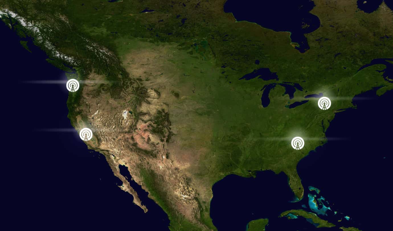
The PENGUIN network is engineered for maximum uptime and fault tolerance. All calls are serviced by four fully independent, isolated, and high-availability data centers distributed across North America. These regions operate in complete isolation from one another, ensuring that an outage in one facility cannot impact the others.
The PENGUIN Network
Incoming Call Routing & Regional Redundancy

Our network is intentionally simple, elegant, and fully redundant.
![]()
When calls enter the PENGUIN network, they are automatically distributed using a round-robin delivery system across all available regions. If any region becomes unreachable for any reason, traffic is instantly routed to the next available site — allowing inbound calling to continue seamlessly.
This architecture delivers several major advantages:
- No inbound call ever fails — unreachable regions are skipped automatically.
- No “Primary” or “Backup” architecture — every region is fully active at all times.
- Massive scalability — traffic is distributed call-by-call across four regions.
- Extreme resilience — even with multiple regional failures, calls continue uninterrupted.
- No cross-region connectivity — eliminating risk of cascading outages.
- Effortless expansion — capacity grows simply by adding more regions.
Call Audio Path
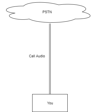
Our audio path is intentionally simple and highly resilient.
When a call is established, the PENGUIN core infrastructure does not sit in the audio path. This ensures that even if an entire region experiences an outage, active calls are not interrupted.
Key benefits include:
- Calls cannot drop due to system issues inside our core network.
- Call quality is never limited by carrier bandwidth or routing bottlenecks.
- No added latency — the call media travels directly between endpoints.
- Total security — we cannot intercept, listen to, or record your audio.
- Maximum clarity — audio stays at the highest possible quality for every call.
Conventional SIP Trunk Provider Design (For Comparison)
Conventional Call Initiation Architecture
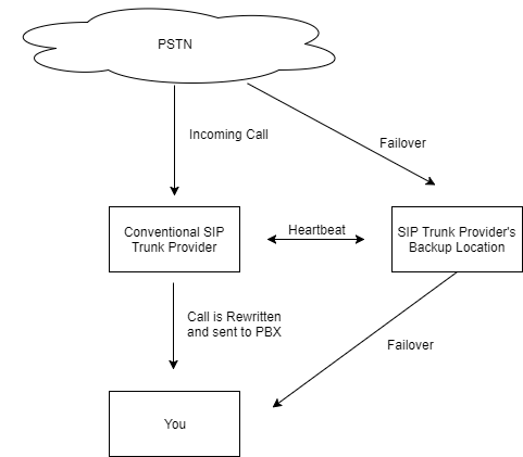
A traditional SIP provider typically uses two data centers — one primary and one standby — with failover triggered only **after** an outage is detected.
This creates several weaknesses:
- Call failures occur before the failover system activates.
- Failover delays (up to several minutes) cause customer-facing outages.
- Misconfigured failover systems often break unexpectedly.
- Regional disasters may impact both the primary and backup locations.
- Backup facilities are often lower grade due to cost cutting.
- Scaling is limited — one active site bottlenecks traffic.
- Cascading outages can occur due to interlinked infrastructure.
Conventional Provider Audio Path
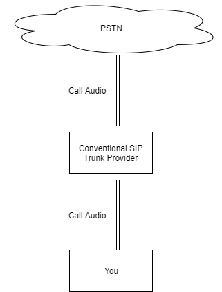
Traditional providers insert themselves into every call’s audio path, creating risks:
- Call quality fluctuates when their core has issues.
- Active calls drop during regional outages.
- Providers with access to media can record or monitor audio.
- Extra router hops introduce audio delay.
- Audio quality is limited by their bandwidth and infrastructure.
- Expensive bandwidth increases customer pricing.